The problem?
You're deep in thought, in the zone, smashing out code. Suddenly, BANG BANG BANG - a knock at the door. Or worse, no knock at all. Just a voice behind you: 'Where is my Spider-Man costume, Dad?' Goodbye focus, hello frustration.
Studies suggest that every interruption can cost up to 30 minutes of lost productivity. Multiply that by a few knocks a day, and it's a wonder I get anything done at all.
I needed a fix - A beacon of `Not Now!` to show the world: I'm busy, please don't disturb me!
The solution?
A lock on the door, a pair of noise cancelling headphones and a device that sits outside my office to indicate that I'm not available right now.
Goals
I have a small list of requirements that I want this project to achieve:
- Wireless - It should be battery-powered, and controllable via an Application Programming Interface (API).
- (Optional) Battery should last 5 days at a minimum.
- Visually appealing - No wires, smooth and sleek, visible by small children.
- Low power notification - If the devices power gets below a specified threshold, send me a notification.
- USB C - Reduce, reuse, recycle.
- (Optional) "doorbell" - If there is something "urgent" that requires my attention, press the doorbell and it will notify me of your presence (with an API to disable the button when it inevitably gets abused).
Device Design
I need a physical device that will sit somewhere outside my office, as a visual aid to notify intruders that I'm currently unavailable. I don't want the device to be huge and unwieldy. It also needs to be functional, by being visible to small human eyes.
I took to the internet and had a look for similar devices, this is where I discovered the "On Air" sign, which is very commonly used in the radio broadcasting field. The sign is displayed outside of the broadcast room and whilst the "Mic is hot", will light up to let others know to be quite whilst broadcasting is happening.
Perfect, this is the exact device I want to build, except I want to control it via an API. I could buy a sign… but where’s the fun in that? I have a 3D printer, a drive to tinker, and an uncanny ability to turn ‘simple’ projects into weeks of obsession and high expense.

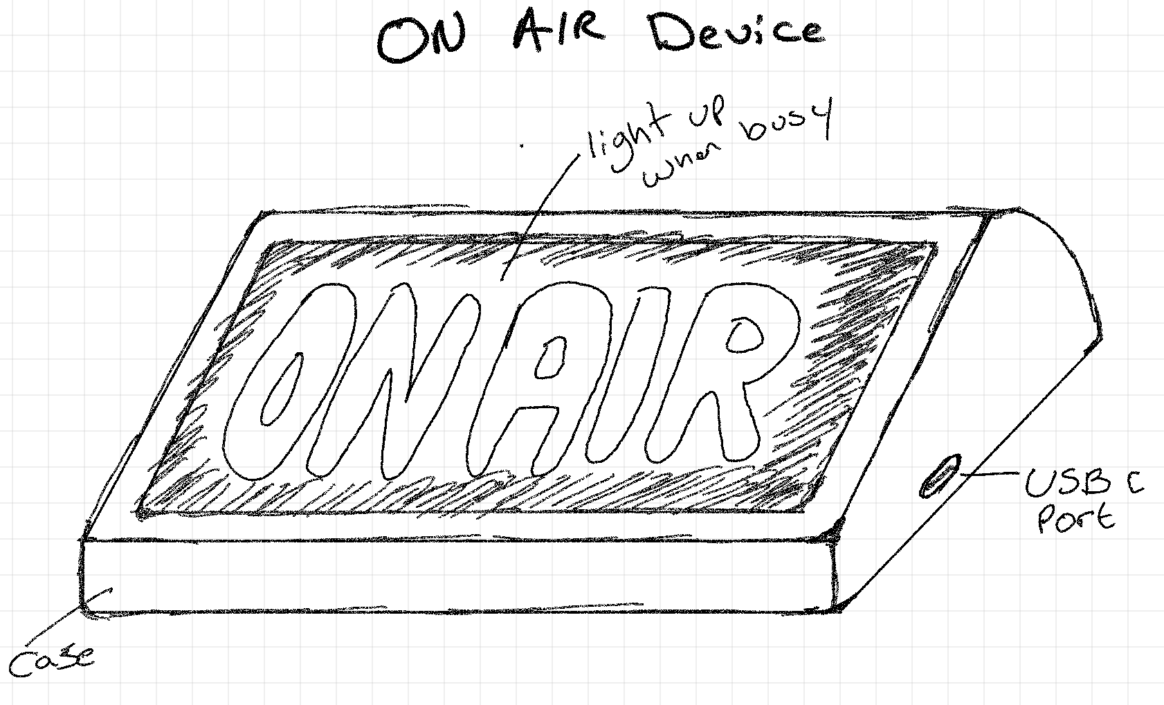
With the idea in my head, I sketched out the device I want to model. I knew that I needed the sign to be on a slight angle to improve the viewing angle for small children.

As you can see from the rough sketch, the on air case is slightly angled, when mounted from the rear, the face of the sign will be angled for an improved viewing experience.
Hardware Choice
I'm a complete beginner when it comes to electronics. So, I need to use what I'm familiar with in an easy to use microcontroller, which takes out a lot of the hard work and knowledge gaps, allowing me to quickly prototype and get the ball rolling.
Enter the FireBeetle 2 ESP32-E. I chose this device for it's simplicity, it also checks of a lot of my goals. The board supports WiFi and Bluetooth dual-mode communication and features an onboard charging circuit which allows charging via USB C.
So, we have a solid foundation, a microcontroller that:
- Allows us to communicate wirelessly.
- Is capable of being powered by a rechargeable battery.
- Is capable of charging the rechargeable battery with an in-built charging circuit.
- Has a USB C connection for charging and programming.
- Supports Arduino programming.
I'm going into this completely blind on power consumption, I have no idea if this microcontroller is power efficient, but we can cross that bridge when we come to it.
Light emitting diodes (LEDs) will be used to indicate when the device is hot (live) by glowing a brilliant red colour. I choose red, because I had some 5mm LEDs laying around and red seems to be the most common colour of choice for these signs.
LiPo Battery for powering the device will be used, I've started with a 3.7v 2500mAh capacity LiPo battery. I had one spare from a failed project (non mobile Spotify device). We shall see how this battery fairs and how often I need to charge it.
Computer Aided Design (CAD)
I now have all the components I think I need and a sketch. Next? CAD!
I'm relatively new to CAD, this was the biggest time sink in learning and forever refining to something useable.
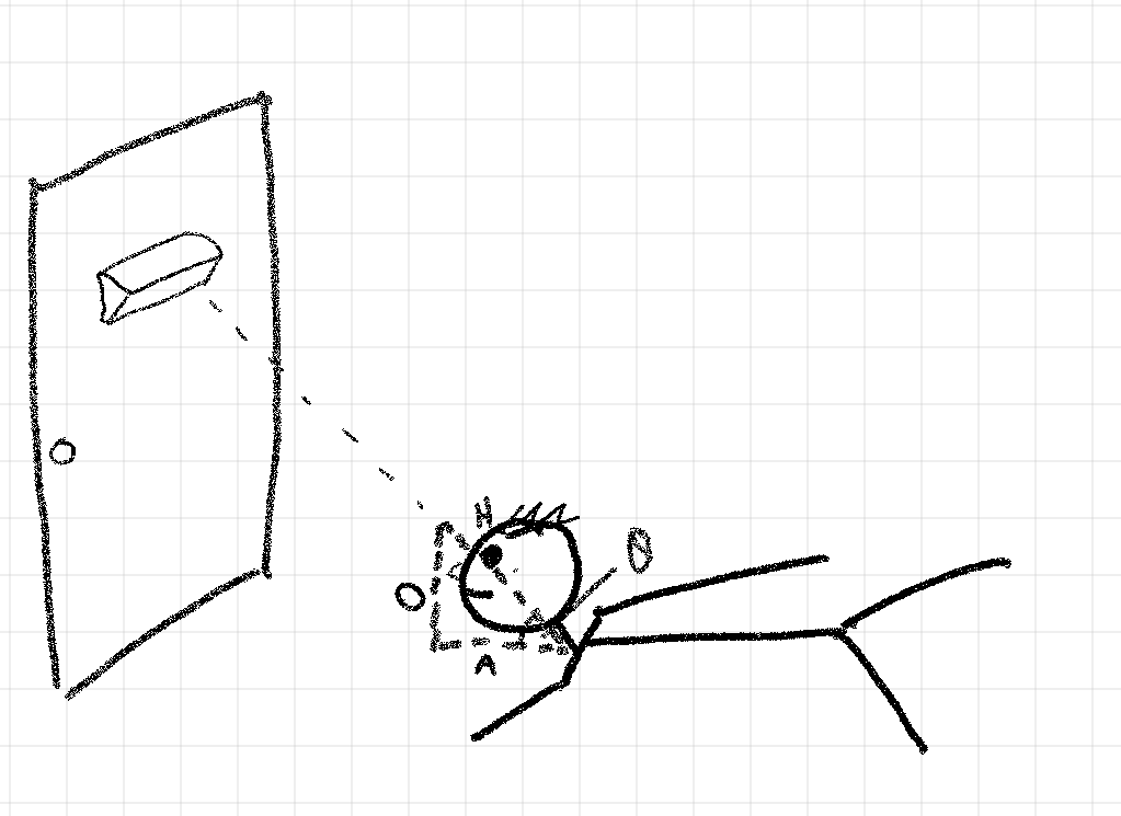
When working with CAD (I use Onshape - Free version) you need measurements. I needed to decide the correct widths, lengths, depths, radius for filets, viewing angle and the internals (microcontroller, LEDs, battery) for mounting. Most of this was at hand and I could simply use callipers to measure dimensions. I must note at this point I purchased clear acrylic pre cut at 150mm by 100mm. This give me the base of the case dimensions since it felt right in the hand and I didn't want to go out and cut the acrylic to smaller sizes. Viewing angle? Well, I lay on the ground outside my office door and looked up to where I thought I'd mount the sign. I then measured the distance from the ground to my eyes, from the tip of my nose to the edge of my shoulders and used trigonometry to work out the viewing angle.

SohCahToa - Thank you secondary school for teaching me Maths! I could work out the viewing angle by applying some simple mathematics. Even if it did involve me lying on the ground with a measuring tape and realising i have a large head.